3 wire regulator rectifier wiring diagram
150cc Scooter Engine Diagram - Wiring Diagrams cars-wiringdiagram. This is a three-wire alternating wiring diagram showing the.

3 Wire Alternator Regulator Diagram Seaboard Marine
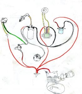
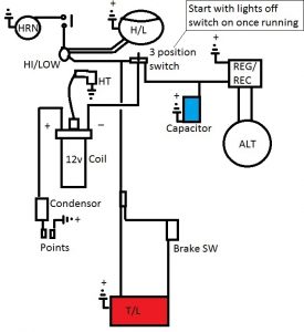
Gy6 headlight wiring diagram.
. This ability to change conductivity with the amount of applied voltage can be used for. Keep up with City news services programs events and more. A solid state rectifier will only drop about 14 volts per diode used so its drop is usually 3 to 6 volts.
31 Component F1. Page 371 19-22 GS500K3 03-MODEL REGULATORRECTIFIER Remove the seat. Mikuni-rs-manualpdf Manufacturer Info Whether its for high performance or just plain old.
Then heat generated is 12V 5V x 05mA 35 Watts. Exciter wire is connected to the L terminal of an alternator and is used to turn on the voltage regulator. The metaloxidesemiconductor field-effect transistor MOSFET MOS-FET or MOS FET is a type of field-effect transistor FET most commonly fabricated by the controlled oxidation of siliconIt has an insulated gate the voltage of which determines the conductivity of the device.
IAC valve ENGINE No4 Cyl. 9 Pics about Gy6 Ignition. Inspect the wires and connections at the back of the alternator at the remote voltage regulator if applicable and at the battery.
The CB750 Enthusiast forums for honda cbr 600 wiring diagram lewis cbr2 full cbr600f2 service manual 1991 ignition temporary fix 1992 wire harness parts voltage rectifier regulator upgrade f3 1996 motorcycle 1994 oem suzuki f4i cbr600f3 label fuse supersport 94 f2 problem forum cb 750 08 cbr600rr engine work 02 96 troubles need bmw e36. Also printed wiring board or PWB is a medium used in electrical and electronic engineering to connect electronic components to one another in a controlled manner. Gy6 Ignition Wiring Diagram - 11.
Travis Buggy Depot July 30 2015. Wiring diagram coil gy6 wire chinese visit engine atv electrical motorcycle circuit quad. 41 Concerning the C1 and C2 capacitor symbols.
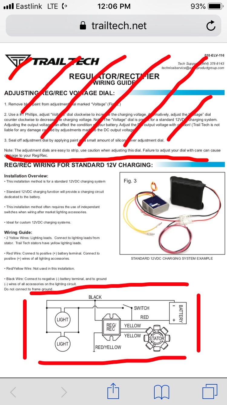
Rectifier that makes use of the full AC wave in both the positive and negative half cycles. The ability of a voltage regulator to maintain a constant. A CRT on a television set is commonly called a picture tube.
These three voltages plus ground define the power requirements for the board. The images may represent electrical waveforms oscilloscope pictures television set computer monitor radar targets or other phenomena. Diconnect the regulatorrectifier couplers.
A small 35mm mp3 player size jack to save room. A diode is a two-terminal electronic component that conducts current primarily in one direction asymmetric conductance. Here is a picture gallery about 4 wire voltage regulator wiring diagram complete with the description of the image please find the image you need.
A tube rectifier will drop more voltage than a solid state rectifier. It takes the form of a laminated sandwich structure of conductive and insulating layers. Each of the conductive layers is designed with an artwork pattern of traces planes and other features.
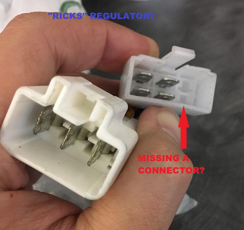
Ricks Motorsport Electrics Hot Shot Series Rectifier Regulator. Check for Wiring Problems. Measure the voltage between the terminals using the multi cir- cuit tester as indicated in the table below.
This is why there are so many colors of wire. If the voltage is not within the specified value replace the regulatorrectifier with a new one. Excitor wire is needed to generate the voltage required for the alternator to start running.
Regulatorrectifier 6p black connector neutral switch wire connector alternatorckp sensor 6p natural connector sidestand switch 3p green connector throttle cable water hoses fuel feed hose fuel pump wire fuel tank drain hose regulatorrectifier wire sidestand switch wire. 4 Wire Voltage Regulator Schematic All Diagram Schematics http8pmmlnicolascouillaudfr4-wire-voltage-regulator-sch. Each Power Destination like a fuse block or Device like turn signals lighting voltage regulator etc has its own combination of colored wires.
Modern personal computers universally use switched-mode power suppliesSome power supplies have a manual switch for selecting input voltage while others automatically adapt to the mains voltage. A ground is often used as the common wiring point or reference in a circuit. A 6 volt wiring system and switches are more than enough to handle 12 volts.
Components For System Control. EBay Motors makes it easy to find parts for cars trucks SUVs motorcycles more. Rectifier regulator easywiring digramssample proform.
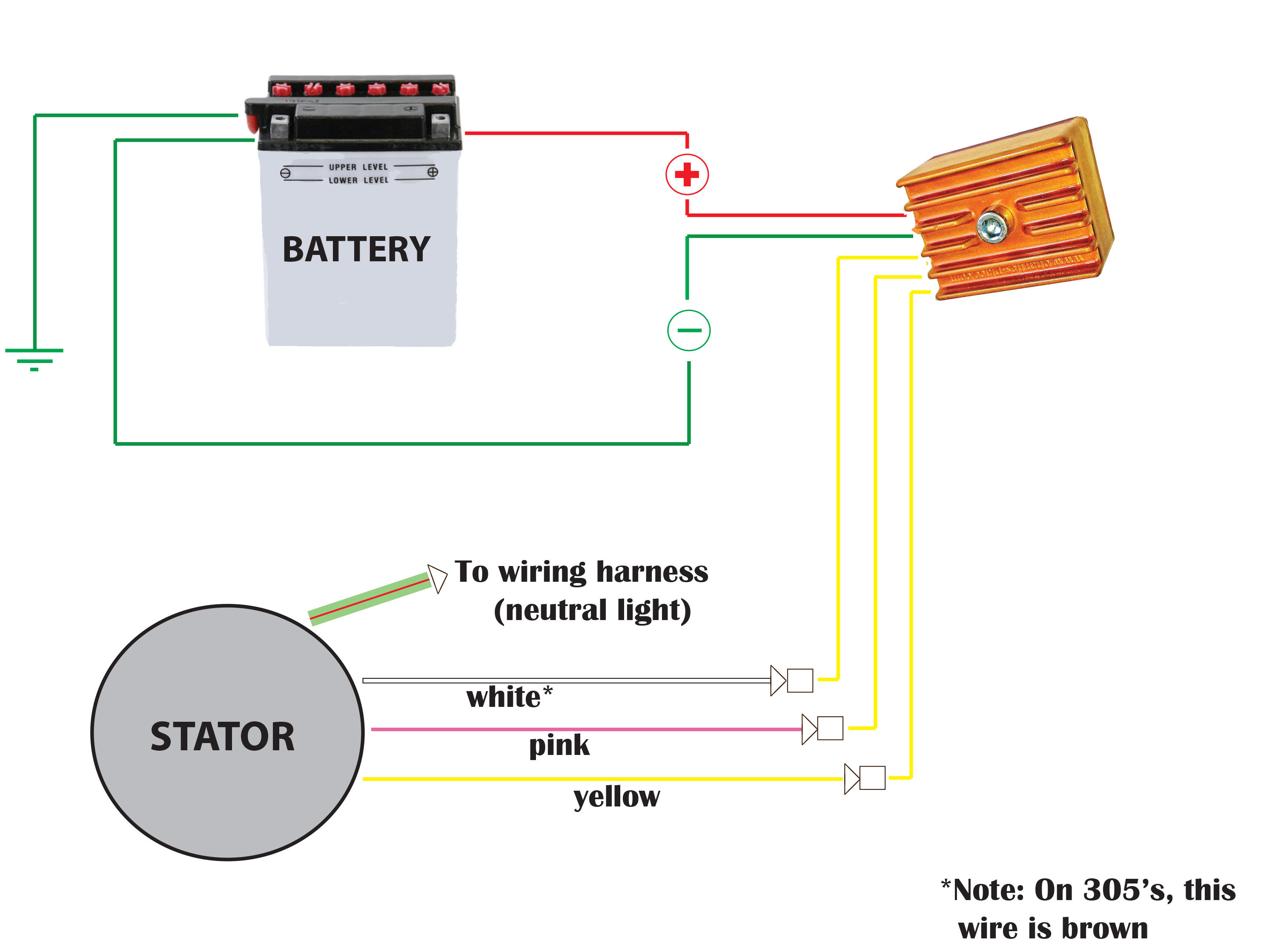
A 3 wire alternator wiring diagram has three wires. The rectifier changes the two-way current into a one-way flow-direct current. 78 means positive and 05 means 5 volts hence this IC is used to supply positive 5 volts DC supply.
KE604176 And Following TM-428 Page 48 Miller Legend. KA840710 And Following SB-148 024-A Figure 9-9. Fuse main MODULE No3 Cyl.
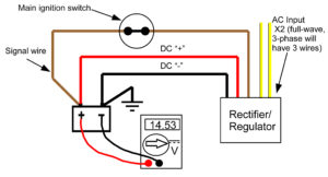
A typical 3-wire alternator wiring diagram with an internal voltage regulator. Official City of Calgary local government Twitter account. A power supply unit PSU converts mains AC to low-voltage regulated DC power for the internal components of a computer.
This is because its heavier because 6v has to carry more amperage. Shop for your next vehicle or start selling in a. An integrated circuit or monolithic integrated circuit also referred to as an IC a chip or a microchip is a set of electronic circuits on one small flat piece or chip of semiconductor material usually silicon.
Page 53 OUTPUT POSITIVE SUPPLY SB-136 249 Figure 9-8. A diode vacuum tube or thermionic diode is a vacuum tube with two electrodes a heated cathode and a plate in which electrons can flow in only one direction. Congratulations this is the correct IEC 60617 symbol for a fuse you will also see this in IEEE 315A Clause 911 the top symbol marked as an IEC symbol.
7805 voltage regulator IC signifies two meanings. Williams System 3-6 Power Wiring Diagram showing the wiring from your AC mains plug right through to the. Using jumper wire connect the through hole via to pin 1 of IC15.
Look for corrosion at the connectors damaged wires and burned and missing insulation that. 32 The rating of the fuse indicated as 025A should be 025 A or 250 mA. The primary charge wire a third wire that can jump between the regulator and the battery stud and the exciter wire.
Wiring Diagram For Engine Control ENGINE CONTROL SYSTEM WIRING DIAGRAM FOR ENGINE CONTROL Fuel injector No1 No2 No3 No4 Cyl. Who sells andersen storm doors. Circuit Diagram For Optional Remote Control Board PC3 Effective With Serial No.
Most modern desktop personal computer power. Circuit Diagram For Voltage Regulator Board PC2 Effective With Serial No. The positive unregulated 12VDC is regulated down to 5VDC via a 7805 regulator at IC11.
It has low ideally zero resistance in one direction and high ideally infinite resistance in the other. Page 26 general information inside boot connectors. Alternator Battery charge coil Rectifier regulator 60A Fuse Ignition coil No1 Cyl.
The 3 wire alternator wiring diagram is considerably less intrusive than it seems as only two additional wires are integrated into the rest of the electrical system. This hot wire can run all over the motorcycle with other different colored wires going from the hot wire to the Power DestinationDevice. Large numbers of tiny MOSFETs metaloxidesemiconductor field-effect transistors integrate into a small chipThis results in circuits that are orders of.
A cathode-ray tube CRT is a vacuum tube containing one or more electron guns which emit electron beams that are manipulated to display images on a phosphorescent screen. So a heat sink can be attached which can absorb heat of 35 watts of power to avoid the IC getting damage. To convert the extra speaker jack replace the tip-to-tip green wire with the 22K resistor and add the 33K.
We even offer a massive selection of new pre-owned classics hot rods exotics vans ATVs RVs boats and more at eBay Motors. A printed circuit board PCB.
The Easiest Way To Hook Up A Mosfet Regulator

Rectifier Regulator Hints N Tips Ulpower News

Recitifer Regulator Signal Wires Rick S Motorsport Electrics Blog And More

Tuzliufi Voltage Regulator Rectifier Compatible With Ezgo E Z Go Medalist Gas Golf Cart 4 Cycle Vehicles Club Car Gas For Columbia S Columbia Parcar 2 Cycle Txt 27739 G01 27739g01 74510 85 3 Wires 14 5v New Z115 Voltage

Norton Commando Wiring Diagram Podtronics
Recitifer Regulator Signal Wires Rick S Motorsport Electrics Blog And More
7 Or 8 Wire Regulator Rectifier Fifth Generation Vfr S Vfrdiscussion

6 Wire Universal 12 Volt Regulator Rectifier Rex S Speed Shop
Wiring Solid State Single Phase Regulators Jrc Engineering Inc

How To Shindengen Mosfet Regulator Rectifier Rc51 Forums

14 100 Type B 3 Phase Field Excited Reg Rec Wiring Diagram Revival Cycles
Wiring Solid State Single Phase Regulators Jrc Engineering Inc
Charlie S Place Type 1 Regulator Rectifier Installation Instructions

Regulator Rectifier Conversion

Testing Your Motorcycle Rectifier

Comprehensive Gl1000 Charging System Troubleshooting Randakk S Blog

Ccdes Voltage Rectifier Regulator 12v 5 Wires For Motorcycle Atv Dirt Quad Scooter 12v Regulator Rectifier Voltage Regulator Replacement Walmart Canada